 |
Dynamo - System Components
|
[ Home ] [ MZ Links ] [ MZ Main Index ] [ Search Site ] [ Join The MZ Riders ]
The MZ 6v DC dynamo charging system is relatively uncomplicated. Its' main
weak points are the carbon
brushes , adjustable
resistor and regulator.
Circuit Diagram Dynamo/Regulator Cut Out - 3 Positions.
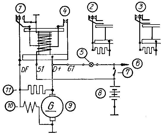
- Lower position
- Suspended Position
- Upper Position
- Reverse Current Switch
- Charge Light
- Ignition, Terminal 15
- Ignition Switch
- Battery 6v 12Ah
- Dynamo 6v 60W
- Field Coil 1.7 - 2.1 ohm
- Adjustable Resistor 4.5 ohm
Back
to Top
Adjustable Resistor
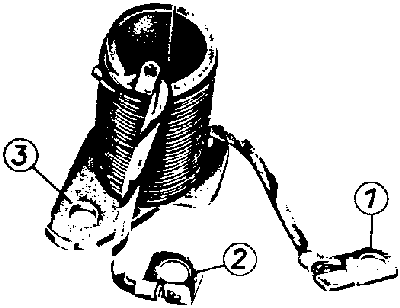
- Long cable, connected to D+ (positive carbon brush)
- Short cable, connected to DF (positive pole of field coil)
- Bracket, negative pole of field coil to earth
Together with the regulator the adjustable resistor keeps the desired voltage
constant.
Current passes through the adjustable resistor when the regulator is in the
suspended position.
In the lower position the adjustable resistor is bridged by the regulator and
thus is of no importance to voltage regulation.
In the upper position the adjustable resistor also has no function to fulfil because the excitation winding is short circuited, thus the voltage breaks down.
If the adjustable resistor is blown, this will be indicated by misfiring,
charred insulation varnish and carbonised contacts on the regulator.
When the charge lamp lights whilst the engine is running this may indicate the
resistor is shorting to earth. Another cause maybe a broken or loose D+ cable at
the regulator or dynamo.
The adjustable resistor is exposed and prone to accidental
damage if you are careless.
Back
to Top
Carbon Brushes
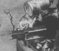
Due to the relatively high current drain of the indicators and stop light and
low output of the dynamo, the carbon brushes should be checked reasonably
frequently (2000 - 3000 miles).
The brushes and their copper cable should be free to move in their holder.
Brushes worn to less than 9mm in length should be replaced
The spring must be engaged in the pin of the brush, or the spring may jam in the
holder.
The copper braid must be a tight fit in the brush. If it is loose this causes
high contact resistance. As a result heats the brush and commutator thereby
destroying the rotor.
The springs themselves must be in good condition to ensure a good contact on the
commutator.
Springs from ballpoint pens don't work - I know!
Back
to Top
Regulator
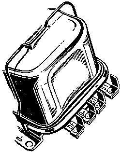 |
The regulator governs the output of the dynamo. It's mechanism consists
primarily of an electro magnetic device which controls the effect of the
dynamo field coils by constantly switching the variable resistor in and
out of circuit.
On the MZ this has three positions
- The lower position, (less than 6.2 v) the battery receives no charge
from the regulator, charge light on.
- The suspended position, (6.5 to 6.9 v) the allows current to the
battery, the charge light is by passed and is extinguished.
- The upper position (over 7.8 v) the excitation windings in the
dynamo are short circuited causing the voltage to break down.
Back
to charge system wiring diagram |
Regulator Specifications
| Voltage |
6v |
| Wattage |
60 W |
| Type |
Three contact positive regulation |
Adjustment of Regulator
The mechanical adjustment of the regulator must be correct before there is
any hope of achieving the correct electrical output.
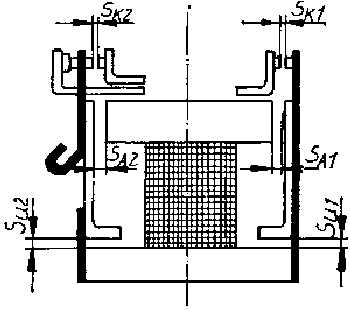 |
- S K1 = 0.4 mm
- S K2 = 0.3 to 0.4 mm
- S A1 = 1.0 mm
- S A2 = 0.9 to 1.0 mm
- S U1 = 0.5 mm
- S U2 = 0.5 mm
|
Values for Electrical Setting of the Regulator.
| |
Regulator
8106.7/1 |
Regulator
8106.7/2
Temperature Compensated |
| Cut in voltage |
6.5 to 6.9 v |
6.5 to 6.9 v |
| Cut out voltage |
5.4 to 6.2 v |
5.4 to 6.2 v |
| No load voltage |
7.1 to 7.6 v |
7.3 to 7.8 v |
Rated voltage
at a current of 10 A
at 1800 to 2200 rpm |
6.2 to 6.8 v |
6.5 to 7.1 v |
Back
to Top
|